
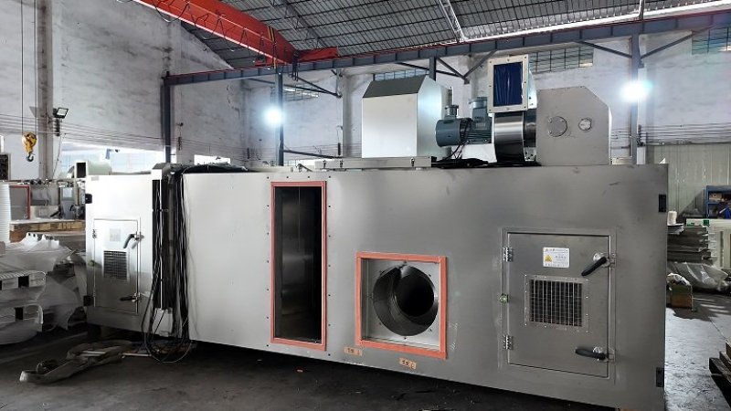
As electrode coating speeds increase from 80 m/min to 150 m/min and beyond, web tension rises accordingly, placing more demanding requirements on the structural rigidity of the oven box. If the oven frame or side panels vibrate noticeably at high operating speeds, it will not only affect equipment stability but may also cause fatigue cracking in welds over time. As a sheet metal fabricator, we ensure rigidity mainly through the following three aspects in structural design and manufacturing.
1. Frame Design: "Bracing" the Frame with Gusset Plates and Reinforcing Ribs
The frame of the oven box is the core structure carrying the entire unit. The fabrication specification is explicit: gusset plates must be used to add strength during frame welding. This is not optional—it is a mandatory process step. The role of gusset plates is to convert the right-angle connections between profile sections into stable triangular structures, preventing the frame from parallelogram deformation under load.
In addition, the connections between the frame and the inner liner use L-shaped and hat-shaped (Ω-profile) brackets, and "the position can be adjusted and the quantity increased based on actual results." This means that during manufacturing, we proactively increase bracket density in stress-concentration areas based on the box length and stress analysis, rather than mechanically spacing them at equal intervals as per the drawing. For the double-layer, 60-meter-long ovens common on high-speed machines, the upper and lower frames are under different loading conditions, so we evaluate each layer separately to ensure the local rigidity of every frame meets requirements.
2. Connecting the Inner Liner to the Frame: Full Welding + Reinforcing Ribs to Prevent "Skin-Bone Separation"
At high web speeds, airflow pulsation inside the box and external vibrations are transmitted to the inner liner. If the liner is only tack-welded or locally fixed to the frame, loosening can occur after long-term operation, causing abnormal noise or even fatigue cracks.
The frame is fully welded (seam welded) throughout, and additional L-shaped or hat-shaped reinforcing ribs are added at the connections between the inner liner and the frame to ensure overall strength. In our actual production, all contact surfaces between the liner and the frame are fully welded. The arrangement of reinforcing ribs considers not only static load-bearing but also the vibration modes during high-speed operation—support points are added at the mid-span of large panels to lower the natural frequency of the thin plates and avoid resonance with the web-running frequency.
3. Roller Mounting Datums: Sheet Metal Accuracy of the Box Determines Web Stability
At high web speeds, electrode tension is transmitted through the rollers to the box structure. If the roller mounting datums on the box are misaligned, the web may deviate at best, and wrinkle or even break at worst. Roller fabrication typically requires coaxiality of ±2 mm front-to-back and roller spacing of ±2 mm. These two specifications appear to be roller requirements, but in fact they test the machining and welding accuracy of the sheet metal components of the box.
Our approach consists of two steps:
First, one-time positioning of mounting datums. Roller brackets or mounting holes are unfolded in the same CNC program during laser cutting, and their relative positions are fixed on the welding fixture when the frame is welded. This avoids the accumulated errors caused by welding the frame first and then laying out and drilling holes manually. The inherent hole-position accuracy of laser cutting is sufficient to support the ±2 mm spacing requirement—the key is to prevent datum shift due to thermal distortion during welding.
Second, datum re-inspection after frame straightening. After frame welding, we control the diagonal error within 3 mm, but this only ensures the squareness of the frame itself. The roller mounting faces require separate inspection—we use a level and a laser line marker to verify the coplanarity and spacing of adjacent mounting faces, confirming they meet the ±2 mm requirement before proceeding to panel assembly. For a double-layer, 60-meter-long oven, the roller mounting datums of the upper and lower layers are inspected independently to avoid systematic deviation between layers.
4. Conclusion
The requirements for oven structural components at high web speeds are ultimately a matter of "dynamics"—vibration, tension, and fatigue under high-speed operation. We do not simply pile on extra material and weight in sheet metal fabrication. Instead, through these three process steps—rational triangular bracing of the frame, full-welded reinforcing ribs for the inner liner, and precise control of roller mounting datums—we strike a balance between weight and rigidity, keeping the box steady and stable under high-speed operating conditions.